

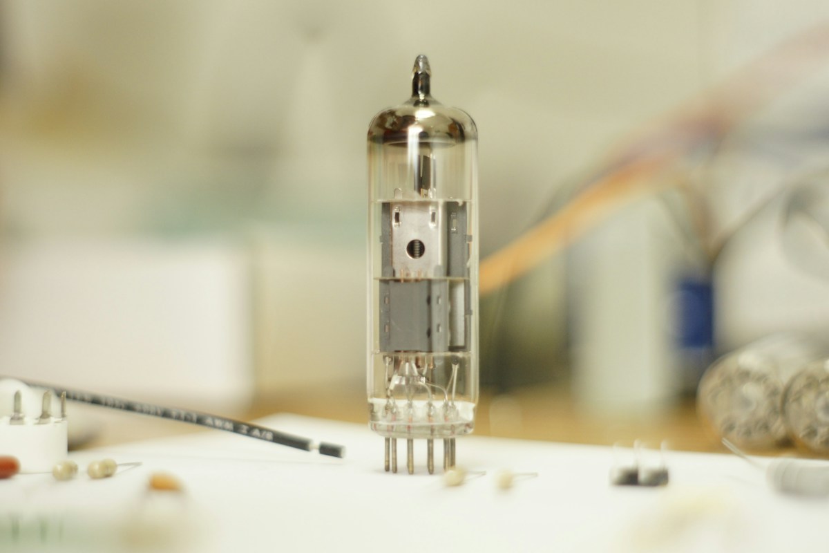
Dim the lights in an acoustically treated listening room, flick the heavy industrial toggle switch on the faceplate of a hand-wired amplifier, and watch a quiet, luminous miracle take place. Beneath clear glass envelopes, tiny tungsten and thorium filaments slowly ignite into a soft, incandescent orange ember. As thermionic heat saturates the vacuum chambers, a faint blue fluorescence dances along the glass walls. Moments later, as the stylus drops into the micro-grooves of an analog master recording, sound floods the room. It does not arrive as an aggressive barrage of quantified digital data; it enters as an organic, breathing physical presence-warm, dimensional, harmonically rich, and possessed of breathtaking spatial depth.
For more than half a century, the high-end audio community and the professional recording industry have been locked in one of the most passionate technical and philosophical debates in modern engineering: vacuum tube amplification (thermionic valves) versus solid-state bipolar and MOSFET transistors. When silicon semiconductors swept across global electronics in the late 1960s, mainstream electrical engineers celebrated the definitive death of the vacuum tube. Solid-state transistors were objectively superior across every standard textbook measurement: they were cheaper, smaller, vastly more energy-efficient, produced virtually zero measurable total harmonic distortion (THD), and delivered massive wattage without overheating.
Yet the vacuum tube refused to die. In fact, in high-end audiophile playback, mastering studios, and legendary electric guitar amplification, thermionic valves are experiencing an unprecedented global renaissance. Why does an archaic nineteenth-century glass bulb often sound subjectively more musical, lifelike, and emotionally arresting than a modern silicon amplifier boasting 0.001% distortion? In this comprehensive technical guide, we dismantle the quantum physics, electrical topologies, harmonic mathematics, and psychoacoustics that separate vacuum tubes from solid-state silicon.
1. Historical Foundations: Edison, Fleming, and the Invention of the Audion
The genesis of thermionic amplification originated from an accidental discovery made by Thomas Alva Edison in 1880 while attempting to resolve why his early carbon-filament incandescent light bulbs blackened internally over time. Edison inserted an independent metal plate inside an evacuated glass bulb and discovered that when the plate was connected to a positive voltage, an electric current mysteriously jumped across the empty vacuum from the hot filament to the cold plate. When connected to a negative voltage, the current ceased completely. This unidirectional electrical flow was christened the Edison Effect.
Edison patented the phenomenon but perceived no practical commercial utility for it. In 1904, British physicist John Ambrose Fleming recognized that the Edison Effect could rectify high-frequency alternating radio waves into direct current, inventing the two-element diode valve (the Fleming Valve). However, the true birth of modern electronics arrived in 1906 when American inventor Lee de Forest made an epochal modification: he inserted a third element-a bent piece of fine wire grid-between the hot filament and the metal plate, christening his invention the Audion (the triode).
De Forest’s control grid transformed electronics forever. By applying a minuscule alternating electrical voltage (such as the weak signal generated by a phonograph pickup or radio antenna) to the grid, the electrostatic field acted as an electrostatic valve, exerting massive control over the flood of electrons traveling from cathode to anode. A tiny voltage fluctuation at the grid was converted into an enormous, proportional current swing at the plate. For the first time in human history, humanity possessed an instrument capable of true electronic amplification.
2. Thermionic Emission Physics: The Quantum Dance of the Electron Cloud
To grasp why vacuum tubes behave so differently from silicon chips, one must explore the fundamental physics of thermionic emission. In solid-state physics, electrons are bound within the crystal lattice of a conductor by a potential energy barrier known as the metal’s work function (Φ). Under normal room temperatures, thermal kinetic energy is insufficient for electrons to escape the metal surface.
When a tube cathode is heated to operating temperatures between 800 and 1,000 degrees Celsius by an internal heater filament, thermal energy excites conduction-band electrons beyond the work function barrier. Electrons literally boil off the cathode surface into the high vacuum, forming a dense, hovering electrostatic cloud of negative charge known as the space charge. The mathematical rate of this electron emission is governed by Richardson’s Law (the Richardson-Dushman Equation):
J = A · T² · exp(-Φ / (k · T))
Where J represents current density, A is Richardson’s constant, T is absolute temperature in Kelvin, Φ is the work function, and k is the Boltzmann constant. In a vacuum tube, electrons move freely through physical, ballistic space at fractions of the speed of light, unimpeded by the atomic crystal lattices, thermal phonon scattering, and microscopic impurity junctions that electrons must navigate inside solid silicon semiconductors. This unimpeded ballistic electron transit accounts for the effortless, unconstrained high-frequency speed that audiophiles describe in top-tier triode amplifiers.
3. Tube Architecture: Triodes, Tetrodes, Beam Power, and Pentodes
As the audio industry demanded higher output power and wider frequency bandwidth throughout the 1920s and 1930s, vacuum tube architecture underwent rapid, sophisticated evolutionary refinements:
- The Triode (e.g., 300B, 2A3, 12AX7): Contains three elements: cathode, control grid, and plate. Triodes are celebrated for their pure, low internal plate resistance and exceptionally linear transfer curves. However, triodes suffer from the Miller Effect-internal parasitic capacitance between grid and plate that causes high-frequency rolloff at high gain levels.
- The Tetrode: Introduced a second grid-the screen grid-placed between the control grid and plate, held at a high positive potential. The screen grid acts as an electrostatic shield, virtually eliminating the Miller Effect and vastly increasing amplification factor. However, tetrodes suffered from secondary emission: high-velocity electrons striking the plate dislodged secondary electrons, which were sucked into the screen grid, causing negative resistance and harsh distortion.
- The Pentode (e.g., EL34, EL84): Solved secondary emission in 1926 by inserting a third grid-the suppressor grid-connected directly to ground or cathode. The negative suppressor repels dislodged secondary electrons back onto the plate, enabling stable, high-efficiency, high-wattage amplification.
- Beam Power Tubes (e.g., 6L6, 6550, KT88): Developed by British and American engineers as an alternative to the pentode. Replaces the wire suppressor grid with curved beam-confining plates that focus electrons into dense sheets, creating a virtual cathode that suppresses secondary emission while delivering immense power and punchy bass dynamics.
4. The Solid-State Revolution: The Physics of the P-N Silicon Junction
On December 23, 1947, at Bell Laboratories in Murray Hill, New Jersey, physicists John Bardeen, Walter Brattain, and William Shockley demonstrated the world’s first working point-contact solid-state transistor, an achievement that earned them the 1956 Nobel Prize in Physics and laid the foundation for the modern digital age.
Unlike vacuum tubes, which control free electrons moving through an evacuated glass envelope, solid-state transistors control electrical current moving through solid semiconductor crystal lattices (primarily silicon doped with trace impurities such as boron or phosphorus). A standard Bipolar Junction Transistor (BJT) consists of alternating N-type (electron-rich) and P-type (hole-rich) semiconductor zones, forming P-N junctions.
When a small base current or gate voltage is applied, it modulates the width of a microscopic depletion region at the junction, controlling the flow of charge carriers between emitter and collector (or source and drain in MOSFETs). Transistors eliminated the heater filament completely: they require zero warmup time, generate a fraction of the waste heat, operate at safe low voltages (15V to 50V compared to the lethal 400V to 1,000V plate voltages of tube amplifiers), and can operate continuously for decades without burning out. By 1975, the global consumer electronics industry had almost completely abandoned vacuum tubes.
5. Amplifier Operating Classes: Class A, Class AB, and Class D Topologies
To understand how both tubes and transistors operate in audio circuits, one must examine amplifier operational classes, which define how an amplifying device is biased along its transfer curve:
Class A Topology: The amplifying device (tube or transistor) is biased to remain continuously active throughout the entire 360-degree cycle of the alternating audio waveform. The device conducts current 100% of the time, even when no music is playing. Class A produces the purest, lowest-distortion audio because it operates entirely within the device’s sweet spot, completely eliminating crossover distortion. However, Class A is notoriously inefficient (typically 20% to 25% efficiency), converting 80% of electrical energy into blistering heat.
Class AB Push-Pull Topology: The standard topology for high-power audio. The circuit uses two complementary devices working in tandem: one handles the positive half of the sound wave, while the other handles the negative half. Class AB biases both devices with a small idle current so they overlap at the zero-crossing point, achieving 50% to 65% efficiency while minimizing crossover artifacts. Virtually all high-wattage tube amps (Marshall, Fender, McIntosh) and high-power solid-state amplifiers utilize Class AB push-pull architecture.
Class D Switching Topology: Modern ultra-compact solid-state amplifiers. Class D does not operate linearly; it uses high-frequency pulse-width modulation (PWM) switching transistors fully on and fully off at speeds exceeding 400 kHz, achieving over 90% efficiency. While magnificent for lightweight PA systems and subwoofers, purist audiophiles often critique Class D for acoustic clinical dryness and high-frequency phase shifts.
6. Harmonic Distortion Profiles: The Decisive Even-Order vs. Odd-Order Divide
Here lies the single most critical scientific explanation for the profound sonic difference between vacuum tubes and solid-state transistors: the Fourier harmonic distribution of distortion.
In electrical engineering, when any amplifying circuit is pushed near its operational limits, it introduces non-linearities that generate new frequencies not present in the original signal. These added frequencies are mathematical integer multiples of the fundamental musical note, known as harmonics. Through Fourier analysis, we can deconstruct these harmonics into two distinct families:
- Even-Order Harmonics (2nd, 4th, 6th, 8th): The 2nd harmonic is exactly one octave above the fundamental note; the 4th harmonic is two octaves above; the 6th harmonic is an octave and a fifth (a musical consonant interval). Even-order harmonics are consonant musical intervals that reinforce the natural acoustic overtones of stringed instruments, brass, and human vocal cords. When an amplifier produces even-order harmonics, the human brain perceives the sound as warm, lush, rich, spacious, and full-bodied.
- Odd-Order Harmonics (3rd, 5th, 7th, 9th): The 3rd harmonic is an octave and a musical fifth, but the 5th, 7th, and 9th harmonics are dissonant, unharmonious intervals that clash violently with the fundamental tone. The human ear is extraordinarily sensitive to high odd-order harmonics, interpreting even microscopic traces (0.01%) as harshness, metallic glare, listening fatigue, and clinical sterility.
Because of the asymmetric, gentle curve of a vacuum tube’s transfer characteristic, tubes generate predominantly second- and fourth-order even harmonics. Bipolar solid-state transistors, by contrast, possess highly symmetrical, sharp transfer characteristics that generate predominantly third-, fifth-, and seventh-order odd harmonics. A tube amplifier producing 1.5% total harmonic distortion often sounds warm, glorious, and natural to the human ear, while a solid-state amplifier producing 0.05% odd-order distortion can sound irritating, abrasive, and fatiguing over extended listening sessions.
7. Overdrive Dynamics and Soft Clipping: Why Tubes Sing
The behavior of an amplifier when pushed beyond its maximum rated electrical power output reveals another monumental divergence between glass valves and silicon chips: clipping dynamics.
When a solid-state transistor reaches its supply voltage rail, it hits an absolute brick wall. The top of the sine wave is sheared off instantly with knife-edge sharpness, creating flat, rectangular square waves. This phenomenon is known as hard clipping. Hard clipping generates a massive cascade of high-frequency odd harmonics, producing a harsh, buzzing, razor-blade distortion that is offensive to the ear and capable of incinerating tweeter voice coils in milliseconds.
A vacuum tube amplifier behaves in fundamentally the opposite manner. When an audio signal exceeds a tube’s linear operating zone, the tube enters a broad, forgiving region of soft clipping and natural saturation. As the signal peaks, the internal plate resistance rises gradually, rounding off the crest of the waveform into a smooth, sinusoidal curve rather than a harsh flat square. Furthermore, as the grid draws current, it induces natural power-supply voltage sag and mild dynamic compression. The peaks of the music are gently cushioned. In electric guitar performance, this soft clipping transforms raw playing into singing, liquid sustain with infinite expressive touch sensitivity; in hi-fi listening, it prevents sudden transient spikes (such as rimshots or fortissimo brass stabs) from sounding brittle or painful.
8. Negative Feedback, TIM Distortion, and High-Frequency Air
In mid-twentieth-century audio design, solid-state engineers faced a major problem: bare silicon transistors exhibit non-linearities and thermal drift. To achieve the immaculate, ruler-flat frequency responses and 0.001% distortion figures demanded by audio consumer magazines, engineers deployed massive amounts of Global Negative Feedback (GNFB).
Negative feedback takes a portion of the amplifier’s output signal, inverts its phase by 180 degrees, and feeds it back into the input stage to cancel out distortion generated along the circuit path. While GNFB works brilliantly on static, continuous sine waves in a laboratory test bench, real musical signals are dynamic, complex, unpredictable transients.
In 1970, Finnish audio researcher Matti Otala published revolutionary research identifying a hidden defect in high-feedback solid-state amplifiers: Transient Intermodulation Distortion (TIM). Because electrical signals take a finite time to travel through the amplifier circuit (propagation delay), rapid, high-frequency musical transients arrive at the input before the corrective negative feedback signal can return from the output. For several microseconds, the input stage is momentarily overdriven, generating severe, audible bursts of intermodulation distortion. Tube amplifiers, possessing inherently linear transfer curves, require very little or zero global negative feedback, completely avoiding TIM distortion and preserving an open, three-dimensional high-frequency “air” and natural acoustic decay.
9. The Output Transformer: The Inductive Heart of the Tube Amplifier
One of the most physically imposing components of any high-end tube amplifier is the output transformer (OPT)-a massive block of laminated silicon steel wound with thousands of turns of insulated copper wire. Solid-state amplifiers rarely have output transformers; why are they mandatory for tube circuits?
The requirement is governed by impedance matching physics. Vacuum tubes operate at very high voltages (300V to 500V) and very low currents, presenting a high internal plate impedance typically between 2,000 and 10,000 ohms. Modern loudspeakers, by contrast, present a very low impedance load of 4 or 8 ohms. Connecting an 8-ohm speaker directly to a 3,000-ohm tube plate would result in near-zero power transfer and instantaneous transformer mismatch.
The output transformer converts the high-voltage, low-current signal of the tubes into the low-voltage, high-current signal required to drive heavy speaker voice coils through magnetic induction. A masterfully engineered transformer (such as those by Partridge, Tamura, Tango, or McIntosh’s patented Unity Coupled circuit) acts as a magnificent magnetic sponge. The magnetic core introduces subtle, euphonic tape-like saturation on bass notes while providing absolute galvanic isolation between the lethal high-voltage plate supply and the loudspeaker terminals, shielding delicate speakers from destructive DC current.
10. Damping Factor and Speaker Interaction: The Acoustic Control Matrix
In electrical audio engineering, Damping Factor (DF) is defined as the ratio of loudspeaker nominal impedance to the amplifier’s internal output impedance:
Damping Factor = Speaker Impedance / Amplifier Output Impedance
Solid-state amplifiers, with their high negative feedback and low-impedance transistor outputs, boast enormous damping factors, often ranging from 200 to over 1,000. A high damping factor acts like an iron fist on the speaker woofer cone: the amplifier exercises absolute electrical braking, snapping the woofer back to center instantly after a bass transient. This produces tight, clinical, lightning-fast bass response, making solid-state amplifiers undisputed champions for driving complex, power-hungry modern multi-way speakers with low impedance dips (down to 2 ohms).
Tube amplifiers, due to the internal resistance of the output transformer windings, exhibit much lower damping factors, typically between 5 and 20. A low damping factor allows the loudspeaker woofer cone to move with slightly more mechanical freedom, resonating naturally with its acoustic enclosure. On high-sensitivity, high-impedance speakers (such as vintage Altec Voice of the Theatre, Klipschorns, or Tannoy Dual Concentrics), this lower damping factor imparts a warm, blooming, resonant acoustic authority to double bass and orchestral timpani that feels organic and physically palpable.
11. Psychoacoustics: Why the Human Brain Craves Thermionic Sound
The ultimate arbiter of audio quality is not an oscilloscope or spectrum analyzer; it is the human auditory cortex. The field of psychoacoustics explains why human listeners consistently exhibit neurological preferences for tube sound over technically “cleaner” solid-state reproduction.
The human hearing mechanism evolved in a natural sonic world governed by mechanical vibrations: wind rustling through foliage, the acoustic resonance of animal vocalizations, and the reverberant decay of thunder. Every natural acoustic sound source generates an orderly series of even- and odd-order harmonic overtones. The human brain uses these harmonic structures to calculate spatial depth, identify the material composition of objects, and gauge emotional nuance.
When an amplifier produces gentle second-harmonic overtones and rounds off harsh transient peaks, it mimics the natural acoustic resonance of physical musical instruments. Neurological studies utilizing EEG brain mapping demonstrate that listening to music reproduced through high-quality tube amplification triggers lower levels of cognitive listening strain, greater frontal alpha-wave activity (indicating deep relaxation), and sustained emotional engagement. The brain does not experience the music as an artificial electronic facsimile; it accepts it as an authentic physical event occurring within the room.
12. The Electric Guitar Legacy: Creating the Sonic DNA of Modern Rock
While the hi-fi world debated the merits of tubes and transistors throughout the 1970s, the electric guitar community settled the question with absolute, unanimous finality: the vacuum tube is king.
For an electric guitarist, the amplifier is not a transparent reproduction device; it is a primary musical instrument. When Leo Fender engineered the 5F6-A Bassman in 1959, and Jim Marshall copied and modified that circuit in London to create the legendary JTM45 and 1959 Super Lead “Plexi,” they birthed the sonic voice of rock and roll. Guitarists from Jimi Hendrix, Eric Clapton, and Jimmy Page to Stevie Ray Vaughan and Eddie Van Halen built their entire legends upon pushing vacuum tubes into harmonic overdrive.
When a guitar player strikes a power chord through an overdriven tube amplifier, the preamp tubes (12AX7s) generate rich harmonic overtones, while the power tubes (EL34s or 6L6s) compress and bloom under plate voltage sag. The amplifier responds dynamically to the player’s fingertips: pick lightly, and the tone is crystalline and chime-like; strike the strings aggressively, and the amplifier roars into rich, singing sustain. Solid-state guitar amplifiers have existed for fifty years, but even the most advanced digital DSP profiling modeling amplifiers (Kemper, Neural DSP, Fractal) dedicate millions of lines of algorithmic code to simulating the physical behavior of glowing glass vacuum tubes.
13. Single-Ended Triodes (SET 300B) and the Zen of Purist Listening
Within the modern high-end audiophile universe, there exists an elite, almost monastic subculture dedicated to the ultimate expression of tube purism: the Single-Ended Triode (SET) amplifier, typically built around the legendary Western Electric 300B directly heated triode tube (originally introduced in 1938 for telephone repeater networks).
A Single-Ended Triode amplifier is a masterpiece of minimalist circuit design. Unlike push-pull amplifiers that split the waveform, an SET amplifier uses a single output tube operating in pure Class A to amplify the entire musical wave from top to bottom. There is zero phase splitting, zero crossover distortion, zero push-pull handoff, and zero global negative feedback. The signal path consists of only three or four components: a volume potentiometer, a driver tube, an output tube, and an output transformer.
An SET 300B amplifier produces a meager 8 watts per channel. On ordinary low-efficiency consumer speakers, 8 watts is hopelessly inadequate. But when paired with ultra-high-efficiency horn-loaded loudspeakers (98dB to 105dB sensitivity), the SET experience is transcendental. The midrange presence, palpable micro-dynamics, and holographic three-dimensional soundstage are uncanny. Vocalists appear suspended in physical air between the speakers, every subtle breath, lip smack, and vibrato rendered with startling, intimate realism.
14. Tube Rolling Culture, Microphonics, and NOS (New Old Stock) Valves
One of the most fascinating and addictive rituals of tube amplifier ownership is the practice of tube rolling-swapping different brands and vintages of tubes within an amplifier to alter its acoustic tonal flavor.
Because tubes are assembled by human hands using microscopic metal plates, grids, and mica spacers, different manufacturing factories imparted unique acoustic characteristics to their valves. Modern audiophiles avidly hunt for New Old Stock (NOS) tubes-unopened, mint-condition vintage valves manufactured between the 1940s and 1970s by legendary historic foundries: Mullard (Blackburn, UK), Telefunken and Siemens (Germany), Amperex (Holland), and RCA, Western Electric, and Sylvania (USA).
A Mullard 12AX7 is renowned for its thick, warm, chocolatey midrange and punchy bass; a Telefunken smooth-plate ECC83 delivers laser-like transparency, extended highs, and surgical imaging; an RCA black-plate 6L6GC produces sweet, glassy highs and legendary bloom. However, tube ownership requires awareness of microphonics: physical vibrations from speakers striking the tube glass can cause internal elements to vibrate like a microphone diaphragm, producing ringing feedback. Audiophiles utilize silicone damping rings and heavy chassis isolation to ensure pure, silent operation.
15. Maintenance, Calibration, and Horological Care: The Biasing Discipline
Unlike solid-state amplifiers that can be plugged in and ignored inside an entertainment cabinet for twenty years, owning a vacuum tube amplifier is an active, tactile relationship akin to maintaining a fine vintage mechanical watch or classic sports car.
The primary maintenance requirement for tube power amplifiers is bias calibration. Biasing involves setting the baseline direct-current (DC) idling voltage applied to the control grids of the power tubes. If bias is set too “cold” (insufficient idle current), the amplifier sounds thin, lifeless, and exhibits crossover distortion. If bias is set too “hot” (excessive idle current), the internal plates will begin to glow bright orange (known as red-plating), leading to thermal runaway, blown fuses, and destroyed tubes within hours.
Many modern tube amplifiers feature automated bias circuits, but purist amplifiers provide top-plate test points, potentiometers, and analog needle meters. Periodically checking and calibrating bias with a digital multimeter ensures optimal sound quality, matches tube aging rates, and extends tube life. Small-signal preamp tubes typically last 5,000 to 10,000 operational hours, while high-power output tubes (KT88s, EL34s) require replacement every 2,000 to 3,000 hours of vigorous listening.
16. Digital Modeling vs. Real Glowing Glass: The Impulse Response Revolution
In the 2020s, digital audio workstations and stage guitar rigs are dominated by sophisticated digital modeling processors and impulse responses (IRs). Supercomputers running neural network machine-learning algorithms measure the non-linear transfer functions of vintage tube circuits down to the millivolt, attempting to replicate every nuance of tube bloom and transformer saturation in pure binary code.
Modern digital modeling has achieved astonishing accuracy: in blind listening tests across compressed YouTube streams or commercial radio mixes, even professional audio engineers struggle to differentiate between a high-end digital Kemper profile and a real miked Marshall Plexi cabinet. For touring musicians, the logistical convenience of carrying a 5-pound digital floorboard instead of four 80-pound tube heads and speaker cabinets is indisputable.
Yet in professional recording studios and private listening rooms, musicians and audiophiles consistently return to physical hardware. Why? Because music is an embodied somatic experience. A digital model produces the sound of a tube amp recorded through a microphone in another room; a real tube amplifier moves air directly against your body. The tactile physical feedback of tubes interacting with real magnetic voice coils, the warmth radiating from the chassis, and the acoustic pressure waves in the room create an intimate physical connection that no digital simulation can ever match.
17. The Modern Vacuum Tube Renaissance: Why Analog Warmth Survives
When the last American and British tube factories shuttered their doors in the 1980s, industry analysts predicted that vacuum tubes would become extinct within a generation. Instead, the global demand for thermionic valves has reached heights unseen since the Apollo moon landings.
Historic foundries like JJ Electronic in Slovakia, Electro-Harmonix and Sovtek in Russia, and Shuguang and PSVANE in China manufacture millions of tubes annually to satisfy voracious global demand. In Rossville, Georgia, Western Electric reopened domestic manufacturing in a state-of-the-art facility, producing legendary 300B triodes using modern cleanroom robotics and metallurgical spectroscopy.
This renaissance is not a nostalgic retreat; it is a conscious aesthetic choice. In an era where music is streamed as weightless, compressed algorithmic data through sterile earbuds, human beings crave weight, presence, and authentic physical warmth. Vacuum tube amplification transforms sound from an invisible digital commodity back into a physical, emotional, and spiritual encounter.
18. Comparative Diagnostic Matrix: Vacuum Tube Amplification vs. Solid-State Transistors
To systematically summarize the electrical, architectural, and acoustic distinctions between vacuum tube and solid-state amplification systems, we must contrast their operating mechanisms across structural engineering dimensions. Understanding these foundational parameters enables audiophiles, studio engineers, and musicians to select the optimal amplification platform tailored to their specific acoustic goals.
The comparative diagnostic matrix below contrasts classical vacuum tube systems with modern solid-state bipolar and MOSFET transistor amplifiers across foundational performance parameters. By examining primary charge carriers, harmonic distortion distributions, overload clipping profiles, damping factors, and maintenance requirements, one gains an authoritative roadmap to audio amplification physics.
Notice that while solid-state amplification delivers unmatched electrical efficiency, ruler-flat frequency precision, and tight bass control for power-hungry modern speakers, vacuum tubes excel in human harmonic consonance, natural dynamic compression, and holographic spatial soundstaging. Master mastering studios frequently pair both: using solid-state amplifiers for clean bass control and tube preamplifiers to inject harmonic air and musical bloom.
| Engineering Parameter | Vacuum Tube Amplification (Valves) | Solid-State Transistors (BJT / MOSFET) |
|---|---|---|
| Primary Charge Carrier | Free electrons moving ballistically through high vacuum | Electrons and holes traversing solid silicon crystal lattice |
| Dominant Harmonic Distortion | 2nd and 4th Even-Order (Musically consonant overtones) | 3rd, 5th, 7th Odd-Order (Abrasive, dissonant harmonics) |
| Overload Clipping Behavior | Soft clipping, natural saturation, forgiving dynamic sag | Hard clipping, sharp square wave shearing, harsh glare |
| Global Negative Feedback (GNFB) | Low or Zero GNFB; immune to Transient Intermodulation (TIM) | High GNFB; prone to TIM transients and phase shifts |
| Damping Factor & Bass Control | Moderate (5 to 20); warm, blooming, resonant bass | High (100 to 1,000+); tight, ultra-fast, controlled bass |
| Operational Longevity | Tubes degrade over time (2,000 – 5,000 hrs); requires biasing | Practically infinite (50,000+ hrs); zero routine maintenance |
Frequently Asked Questions About Vacuum Tubes and Solid-State Audio
Why do tube amplifiers sound warmer than solid-state amplifiers?
Tube amplifiers produce predominantly second-order even harmonic distortion, which mathematically reinforces musical octaves and consonants. Solid-state amplifiers produce predominantly odd-order harmonics (3rd, 5th, 7th), which the human ear interprets as harsh, metallic, and fatiguing.
What is the difference between Class A and Class AB amplifier operation?
In Class A amplifiers, the output tubes or transistors conduct electrical current 100% of the time, completely eliminating crossover distortion at the expense of high heat and low efficiency. Class AB uses push-pull pairs that alternate conduction, achieving higher power and efficiency with minimal distortion.
Do vacuum tubes wear out over time?
Yes. Because the cathode relies on chemical coatings that boil off electrons under high heat, tubes slowly deplete their emissions over time. Power output tubes typically last 2,000 to 3,000 hours of playing time, while small preamp tubes can last 5,000 to 10,000 hours before needing replacement.
What does ‘tube rolling’ mean in audiophile terminology?
Tube rolling refers to the practice of swapping different brands, variants, or vintage New Old Stock (NOS) tubes into an amplifier to subtly adjust its tonal balance, soundstage depth, and frequency response to personal preference.
Why do tube amplifiers require heavy output transformers?
Vacuum tubes operate at high voltages and low currents, resulting in a high output impedance (several thousand ohms). Loudspeakers operate at very low impedances (4 or 8 ohms). The output transformer magnetically converts the high-impedance tube signal into low-impedance current to drive speaker cones.
What does soft clipping mean compared to hard clipping?
When pushed beyond their maximum power limit, solid-state transistors clip harshly, squaring off the waveform with sharp corners that create abrasive distortion. Tubes enter soft clipping, gently rounding off the peaks like natural dynamic compression, which sounds musical and pleasant to the ear.
Can a solid-state amplifier damage speakers during clipping?
Yes. When a solid-state amplifier clips harshly, it sends intense high-frequency square wave energy to the speaker’s delicate tweeters, which can quickly overheat and incinerate voice coils. Tube soft clipping is far more forgiving on speaker drivers.
Why is biasing a tube amplifier necessary?
Biasing sets the baseline idle current flowing through the power tubes when no music is playing. If set too cold, the amp sounds thin and distorted; if set too hot, the tubes will red-plate and burn out rapidly. Proper biasing ensures maximum tonal fidelity and tube longevity.
19. Embracing the Thermionic Fire of Musical Reproduction
In our headlong rush toward total digital convergence, where music has been reduced to compressed data packets streaming over invisible networks into disposable plastic chips, we risk losing our connection to the physical magic of sound. An electrical circuit that is mathematically flawless on paper can still leave the human soul cold, untouched, and uninspired.
The enduring miracle of the vacuum tube lies in its imperfect, organic humanity. When you sit before a glowing thermionic amplifier, you are bearing witness to the living physics of the cosmos: thermal energy liberating electrons into a vacuum, guided by fine wire grids, and transformed into warm, dimensional music that resonates with the ancient wiring of the human heart. In the gentle amber glow of vacuum tubes, music is not merely heard; it is felt, experienced, and cherished as an enduring sanctuary of human art.


1 Comment
Pingback: Blue Note Records Acoustic Identity: Rudy Van Gelder and the Sonic Engineering of Classic Hard Bop – Anemoia