

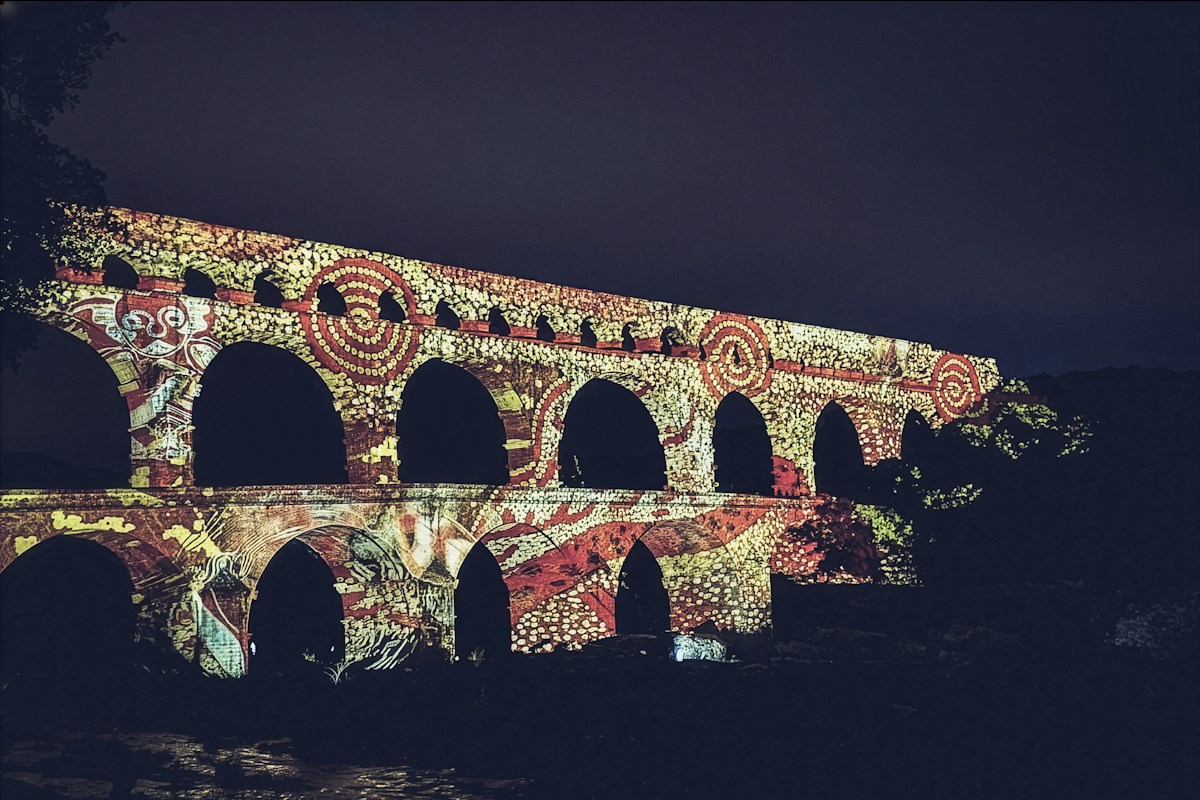
Stand beneath the soaring, three-tiered golden limestone arches of the Pont du Gard in southern France or walk along the silent, travertine spine of the Aqua Claudia stretching across the Roman Campagna, and you are witnessing one of the supreme technological achievements in human civil engineering. Long before the invention of electric water pumps, cast-iron pressure mains, reinforced steel girders, or mechanized excavation equipment, Roman hydraulic engineers mastered the invisible, relentless force of pure planetary gravity. Across five centuries, they designed and built a continental infrastructure network of enclosed stone channels, subterranean mountain tunnels, siphon systems, and arcaded bridges that channeled hundreds of millions of gallons of fresh spring water daily over distances exceeding fifty miles to sustain imperial urban civilizations.
Water was not merely an aesthetic luxury or a casual domestic convenience for classical antiquity; it was the biological, economic, and political circulatory system of Roman civilization. Abundant flowing water powered bustling public bath complexes that reinforced civic hygiene and imperial propaganda, flushed complex subterranean sewer systems that mitigated epidemic contagion, spun mechanical industrial waterwheels that ground grain for millions, and flowed continuously through neighborhood public fountains to quench the thirst of plebeian tenements. The mastery of clean, reliable municipal water defined Roman urban superiority across the Mediterranean basin, from the arid desert fringes of North Africa and Syria to the damp river valleys of Gaul and Britannia.
In this authoritative historical, civil engineering, and archaeological treatise, we deconstruct the architecture and hydraulic physics of the Roman aqueduct system. We explore the surveying instruments described by Vitruvius and Frontinus, calculate the microscopic gradient math required to maintain laminar flow across rugged topography, examine the volcanic chemistry of pozzolana hydraulic concrete, unpack the fluid dynamics of high-pressure inverted lead siphons, analyze the administrative bureaucracy of imperial water distribution, and trace the tragic structural decline that accompanied the fall of the Western Roman Empire.
1. The Vitruvian Doctrine: Chorobates, Dioptra, and Surveying the Grade
The foundational marvel of every Roman aqueduct did not lie in its visible stone arches, but in the unseen precision of its surveying. Because the Romans possessed no motorized pumps to lift water over hills or force it through long horizontal deadlocks, every single foot of an aqueduct conduit had to slope continuously downward from its high mountain spring source to the city distribution hub under the influence of gravity alone.
To establish this unbroken descent across dozens of miles of rugged mountain canyons, rolling hills, and marshy floodplains, Roman surveyors-known as mensores and agrimensores-relied on sophisticated optical and leveling instruments detailed by architect Vitruvius in De Architectura and Sextus Julius Frontinus in De Aquaeductu Urbis Romae. The primary instrument was the chorobates, a massive twenty-foot-long wooden bench supported by four sturdy legs. At each end of the bench hung two weighted plumb lines suspended alongside carved vertical calibration marks. Along the upper surface of the bench ran a five-foot-long carved groove filled with water, which served as a sensitive spirit level when wind buffeted the plumb bobs.
Working alongside the chorobates was the groma, a cross-shaped sighting tool used to lay out precise right angles and straight lines across vast landscapes, and the dioptra, an early precursor to the modern theodolite described by Hero of Alexandria, which utilized calibrated gear drives and water-level tubes to measure vertical inclinations and horizontal azimuths. Sighting through brass peep-holes across leveled rods over hundreds of individual intermediate stations, Roman surveyors mapped contours with tolerances that rival contemporary laser transit benchmarks, often maintaining slopes as gentle as one foot of fall per thousand feet of horizontal distance.
2. Hydraulic Gradient Math: Calculating Uniform Slopes Over Hundreds of Kilometers
Calculating the hydraulic gradient of an aqueduct was a delicate balancing act between destructive hydrodynamic erosion and stagnant sediment accumulation. If the channel sloped too steeply, the rushing torrent of water would accelerate past critical velocities, generating destructive cavitation, eroding stone lining mortar, and rupturing conduit sidewalls around sharp turns. If the slope was too shallow, water flow would become sluggish, allowing suspended silt and heavy mineral deposits to settle, choking the channel and reducing volumetric discharge.
Vitruvius recommended a minimum gradient of one in two hundred (0.5 percent), but in practical field engineering across rugged imperial terrain, Roman surveyors frequently operated far below this threshold to overcome natural topographical obstacles. The great aqueduct of Nimes, which spans fifty kilometers to deliver water from the Eure springs at Uzes to the city fountain terminal, features an average vertical fall of only seventeen meters across its entire length. This translates to a breathtakingly gentle gradient of approximately 34 centimeters per kilometer, or roughly 1:3,000.
To achieve this miraculous consistency, Roman engineers divided long courses into distinct hydraulic sectors. Across flat plains or around contour skirts, gradients were flattened to preserve gravitational potential head. Approaching valleys or river crossings, gradients were subtly steepened before bridges or siphons to accelerate velocity and prevent water backing up into upstream inspection shafts. These complex fluid dynamic calculations were executed without algebra or calculus, relying entirely on empirical geometric ratios, field observation of natural stream dynamics, and standardized measuring rods.
3. Subterranean Sinuous Tunnels: Cuniculi and Shaft Sinking Across Mountains
Popular modern imagination envisions Roman aqueducts exclusively as endless lines of monumental stone arches marching across open fields. In reality, elevated bridges and arcades accounted for less than twenty percent of the total imperial aqueduct network; more than eighty percent of an aqueduct’s total length ran entirely underground as buried masonry channels or deep mountain tunnels.
Subterranean routing offered decisive strategic and engineering advantages:
- Thermal and Biological Insulation: Subterranean conduits shielded cold alpine spring water from baking Mediterranean summer heat, preventing evaporation and inhibiting the growth of algae, bacteria, and insect vectors.
- Structural Protection: Buried masonry was immune to wind loading, earthquakes, winter frost-heave cycles, and soil surface erosion.
- Military Security: In times of foreign invasion or rebellion, subterranean channels could not be easily located or severed by besieging armies attempting to cut the city water supply.
To excavate tunnels through solid limestone mountains-such as the three-mile-long tunnel penetrating Mount Salviano for the Fucine Lake drainage project-Roman miners employed the qanat or shaft-sinking method (putei). Surveyors lined up vertical alignment cairns across the mountain ridge. Work crews then sank vertical shafts spaced thirty to fifty meters apart directly into the bedrock. Once the shafts reached the calculated invert level of the aqueduct conduit, miners turned ninety degrees and tunneled horizontally in both directions simultaneously.
This brilliant technique multiplied the active excavation faces exponentially: rather than two miners chipping away at the opposite ends of a mountain, hundreds of slaves and legionaries could dig simultaneously across twenty shaft stations. Smoke from oil lamps and dust was cleared using manual bellows and linen windsails, while spoil was hauled to the surface in leather buckets via hand-cranked wooden capstans.
4. Opus Caementicium: Pozzolana Concrete and Impermeable Hydraulic Mortar
The monumental durability of Roman hydraulic architecture was made possible by a revolutionary material discovery: hydraulic concrete (opus caementicium) bonded with volcanic pozzolana.
Traditional slaked lime mortar made from burned calcium carbonate hardens through carbonation: it must absorb carbon dioxide from ambient air to crystallize into solid limestone. Consequently, ordinary lime mortar will never cure or set while submerged under water; it dissolves into a mushy slurry. Roman builders, however, discovered vast deposits of reactive aluminosilicate volcanic ash around Pozzuoli near the Bay of Naples (pulvis puteolanus) and in the Alban Hills south of Rome.
When finely crushed pozzolana ash was blended with quicklime and water, it triggered an exothermic chemical reaction forming calcium-silicate-hydrate and calcium-aluminum-silicate-hydrate minerals. This volcanic mortar did not require air to cure; it set underwater into an impermeable artificial rock that grew stronger, rather than weaker, when exposed to continuous moisture. Roman aqueduct interiors were coated with multiple coats of specialized hydraulic plaster known as opus signinum (composed of lime, pozzolana, and crushed terracotta tile sherds), burnished smooth with wooden floats to create a glass-like waterproof skin that resisted dynamic water pressure for centuries.
5. Arcaded Superstructures: Multi-Tiered Arches and Structural Wind Loads
When an aqueduct route encountered deep river ravines, depressions, or the final flat expanses of plains surrounding a metropolis, subterranean tunneling was no longer viable. To preserve the hydraulic head without allowing the channel to plunge to the valley floor, Roman architects erected towering stone arcades and monumental aqueduct bridges.
The structural genius of the Roman arcade lay in the semicircular voussoir arch. Constructed from wedge-shaped blocks of dressed ashlar masonry or cast concrete faced with fired brick, the arch translates the immense vertical dead weight of the water channel, masonry sidewalls, and vaulted roof into lateral diagonal thrust lines directed down into massive vertical piers. By linking arches in continuous longitudinal colonnades, the horizontal thrust of each arch is counterbalanced by the opposing thrust of its neighbor, creating a self-stabilizing structural chain.
To span immense chasms without building impossibly slender, buckling single piers, Roman engineers stacked arches into multiple vertical tiers. On the world-renowned Pont du Gard in southern France-which soars forty-nine meters above the Gardon River-three tiers of arches create a rigid structural lattice. The bottom tier features six massive arches carrying a road bridge; the middle tier consists of eleven arches; and the top tier carries thirty-five small arches supporting the covered water conduit (specus). Piers were shaped with triangular stone cutwaters facing upstream to deflect raging flash floods, while projecting stone corbels were left permanently in place to support wooden maintenance scaffolding for future generations.
6. Siphons and Inverted High-Pressure Lead Pipe Enclosures
While masonry bridges were ideal for crossing valleys up to fifty meters deep, deeper river gorges-such as those surrounding Lyon (Lugdunum) in Roman Gaul-presented valleys over one hundred meters deep and a kilometer wide. Building stone arcades to such dizzying heights exceeded the structural compressive limits of unreinforced masonry and invited catastrophic collapse under Atlantic wind buffeting. In these extreme terrains, Roman engineers deployed one of their most sophisticated hydraulic innovations: the inverted siphon.
Operating on the fundamental hydrostatic principle of communicating vessels, an inverted siphon allowed water to plunge down one valley slope under gravitational momentum and rise up the opposing slope to an exit basin located slightly below the entrance header tank. However, because the water conduit descended into a deep depression, the static hydrostatic pressure at the valley floor reached staggering levels, often exceeding ten to fifteen atmospheres (150 to 220 pounds per square inch).
Masonry channels and terracotta pipes would shatter instantly under such bursting pressures. To withstand the load, Roman engineers cast massive, thick-walled lead pipes (fistulae) soldered with molten lead-tin alloys. Because a single large lead pipe would burst under hoop stress, engineers divided the flow from the masonry aqueduct into eight to twelve parallel lead pipes running side-by-side across the valley floor atop a low stone bridge (the venter). These high-pressure lead siphons required hundreds of tons of refined lead ore mined in Britannia and Hispania, testifying to the vast industrial metallurgical supply chains commanded by the Roman state.
7. Castellum Aquae: Distribution Terminals and Flow Division
When an aqueduct completed its long gravitational journey and arrived at the periphery of an imperial city, it discharged into a massive, fortified municipal distribution terminal known as the castellum aquae. The most perfectly preserved example of this infrastructure survives today at Pompeii, situated at the city’s highest geographical elevation near the Vesuvius Gate.
The castellum aquae functioned as a centralized hydraulic clearinghouse, pressure-dampening chamber, and flow-diversion manifold. Raw water poured from the aqueduct conduit into a circular settling chamber, where remaining debris was filtered through fine bronze grates. From this central reservoir, the water spilled over calibrated bronze weirs into separate distribution channels serving distinct urban sectors:
- Public Basins and Fountains (Lacus): The highest priority allocation, guaranteed to flow continuously even during severe seasonal droughts so that common citizens always had access to free, fresh drinking water within a few hundred feet of their homes.
- Public Baths (Thermae) and Theaters: The second priority allocation, supplying the enormous heating boilers, cold plunge pools, and decorative water cascades of civic leisure complexes.
- Private Domestic Concessions: The lowest priority allocation, leased to wealthy patrician villas, private gardens, and commercial industrial enterprises. During water shortages, the sluice gates feeding private conduits were physically shut down to protect the public fountains.
8. Calix and Water Rights: Measuring Orifices and Imperial Water Thefts
To control private water concessions and prevent the looting of municipal supplies, the Roman imperial water board (curator aquarum) developed a standardized legal and metrological measurement system based on a calibrated bronze pipe nozzle known as the calix.
Because lead pipe was soft and malleable, corrupt citizens and dishonest plumbers frequently hammered pipes into oval shapes or bored unauthorized taps directly into public mains-a widespread crime known as aquilex or water puncture. To prevent tampering, Roman law mandated that all private connections tap the public reservoir through an official, cast-bronze calix of strictly certified diameter, stamped with the seal of the emperor and the watermark of the water commissioner.
The fundamental unit of hydraulic measurement was the quinaria, defined by Frontinus as a circular pipe with a diameter of five-fourths of a Roman digit (roughly 2.3 centimeters or 0.9 inches), yielding an internal cross-sectional area of approximately 4.2 square centimeters. Frontinus compiled exhaustive bureaucratic registers comparing the total volume entering Rome via each aqueduct conduit with the sum of all legal quinariae allocated to public basins, baths, and private concessions. In doing so, Frontinus uncovered massive structural corruption: nearly forty percent of Rome’s daily water volume was being stolen along the route through secret illegal branch pipes bribed into existence by wealthy estate owners and corrupt imperial water wardens.
9. Settle Tanks (Piscinae Limariae): Sediment Separation and Aeration
Alpine and volcanic spring water carried massive loads of suspended physical debris: sand grains, dissolved silt, leaf litter, and mineral carbonates. If allowed to enter the narrow distribution pipes and urban lead mains, this grit would rapidly scour internal linings, clog bronze calices, and choke delicate fountain nozzles.
To purify the water flow before it entered populated districts, Roman engineers integrated specialized desilting complexes called piscinae limariae (settling basins or sediment tanks) at strategic intervals along the aqueduct line and immediately upstream of the urban castellum aquae. A piscina limaria was typically configured as a two-story, four-compartment vaulted masonry chamber built from waterproof pozzolana concrete.
The internal geometry of the piscina limaria operated on classical sedimentation principles:
- Cross-Sectional Expansion: As rushing water entered the cavernous tank, the effective cross-sectional area expanded tenfold, instantly slowing fluid velocity from a turbulent rush to a gentle, placid crawl.
- Gravity Settling: Deprived of velocity, suspended sand, grit, and heavy mineral particulates settled to the concave sump floor of the lower chambers.
- Baffle Separation: Water had to spill over an elevated central weir and pass through perforated limestone baffle screens to enter the upper discharge chamber, ensuring that only clear, clarified water returned to the main conduit.
- Scour Valves: The lower sump chambers were fitted with heavy bronze sluice valves that maintenance crews opened periodically to flush concentrated silt out into adjacent agricultural drainage ditches.
10. Sinter and Calcite Accumulation: Maintenance, Descaling, and Slave Labor
While sand and silt were easily trapped in settling tanks, Roman aqueducts sourced from limestone aquifers-such as the springs feeding the Aqua Marcia and Anio Novus-faced an even more insidious chemical threat: calcium carbonate encrustation (calcareous sinter or travertine scale).
Limestone groundwater is naturally saturated with dissolved calcium bicarbonate ((HCO_3)_2$). As the water tumbled through open-channel aqueducts, atmospheric contact triggered degassing of dissolved carbon dioxide ($), causing calcium carbonate ($) to precipitate out of solution and crystallize onto the masonry sidewalls and floor of the conduit. Year after year, rock-hard calcite scale built up in rhythmic concentric layers, narrowing the cross-sectional area of the channel and dramatically increasing frictional resistance against the water current.
On the Eifel Aqueduct supplying Roman Cologne (Colonia Claudia Ara Agrippinensium), calcite encrustations reached thicknesses of up to thirty centimeters, threatening to choke the water supply completely. Maintaining these conduits demanded continuous, grueling physical labor executed by public maintenance slaves (the aquarii). Working in pitch darkness inside the cramped, waist-high conduits by the dim glow of terracotta oil lamps, crews wielded pickaxes and broad chisels to chip rock-hard sinter from the masonry walls. This quarried aqueduct sinter was so dense and beautifully banded that in the Middle Ages, builders recycled it as decorative “Eifel marble” for church columns and altar screens.
11. Case Study: The Aqua Claudia and Anio Novus of Imperial Rome
The pinnacle of Roman hydraulic grandeur was achieved during the Julio-Claudian dynasty with the simultaneous construction of the Aqua Claudia and the Anio Novus, initiated by Emperor Caligula in 38 AD and completed by Emperor Claudius in 52 AD.
The Aqua Claudia tapped the crystal-clear, cold springs of the Anio valley sixty-nine kilometers east of Rome, while the Anio Novus drew from the direct flow of the Anio River near Subiaco, traveling eighty-seven kilometers across mountains, tunnels, and open valleys. As these two massive systems approached the final fourteen kilometers across the rolling Roman Campagna toward the Porta Maggiore, engineers combined them into an awe-inspiring double-decker structural arcade.
Supported on soaring, rusticated travertine piers reaching heights of over twenty-eight meters (nearly one hundred feet), the monumental arcade carried two stacked masonry conduits: the Aqua Claudia occupied the lower channel, while the Anio Novus ran directly on top of its vaulted ceiling in the upper channel. Together, these two aqueducts discharged nearly three hundred thousand cubic meters of fresh water into Rome every twenty-four hours, dramatically elevating the capital’s total water influx to over one million cubic meters daily: an astonishing daily per capita water volume exceeding that of most twenty-first-century European metropolises.
12. Provincial Marvel: Pont du Gard and the Nimes Aqueduct Sinuous Route
Nowhere is Roman hydraulic daring more vividly preserved than at the Pont du Gard, the crowning jewel of the fifty-kilometer-long aqueduct that supplied the Gallic city of Nemausus (modern Nimes) during the first century AD.
The straight-line geographical distance between the Eure springs at Uzes and Nimes is only twenty kilometers. However, the direct path is blocked by the impassable limestone mass of the Garrigues plateau. Unable to drill a twenty-kilometer deep tunnel through the mountain ridge, Roman surveyors traced a brilliant, sinuous semicircular arc around the western flank of the hills, hugging the natural topographical contours to maintain an unbroken downward slope.
Where this snaking route encountered the steep, three-hundred-meter-wide canyon of the Gardon River, Roman master builders constructed the Pont du Gard. Erected without mortar from more than fifty thousand tons of soft yellow shelly limestone quarried directly from the adjacent riverbanks, the bridge stands forty-nine meters tall. The massive stones of the lower arches-some weighing up to six tons each-were hoisted into place using human treadwheel cranes and friction lewis irons, dry-fitted with interlocking precision so perfect that the structure has withstood two millennia of violent Mediterranean flash floods without shifting an inch.
13. North African Wonders: The Aqueduct of Carthage and Zaghouan Springs
In the arid landscapes of Roman North Africa (the imperial grain basket), hydraulic engineering was a matter of sheer biological survival. Following the destruction of Punic Carthage and its re-founding as a premier Roman metropolis by Julius Caesar and Augustus, Emperor Hadrian commissioned one of the longest continuous aqueduct networks in the ancient world: the Aqueduct of Carthage (Zaghouan Aqueduct).
Spanning an astounding 132 kilometers from the high mountain springs of Djebel Zaghouan to the monumental Cisterns of La Malga at Carthage, the Zaghouan Aqueduct traversed harsh desert plateaus, jagged ravines, and saline depressions. At the source, Roman architects erected the magnificent Temple of the Water (the Nymphaeum of Zaghouan), an ornate semicircular colonnade enshrining the sacred bubbling springs.
Across the vast Miliana river valley, the aqueduct rose onto monumental arcades stretching for more than seventeen kilometers, with sandstone arches towering over twenty meters high. At Carthage, the aqueduct terminated in the legendary La Malga cistern complex: fifteen parallel barrel-vaulted masonry reservoirs capable of storing over sixty thousand cubic meters (sixteen million gallons) of water to supply the colossal Antonine Baths and sustain the civilian populace through prolonged desert droughts.
14. The Barbegal Watermills: Industrial Power and Mass Milling Complex
While the cultural role of Roman aqueducts in supplying public baths and decorative fountains is widely celebrated, archaeological excavations have revealed an equally revolutionary application: industrial hydraulic power generation. The supreme testament to Roman industrial automation is the Barbegal milling complex near Arles in southern France.
Dating to the second century AD, Barbegal was supplied by a dedicated branch conduit split from the main Arles aqueduct. Where the aqueduct pierced a high limestone ridge through a rock-cut cleft, engineers directed the water down a steep, thirty-degree rocky hillside descending nineteen vertical meters. Instead of wasting this hydraulic head, Roman engineers constructed a tiered factory complex housing sixteen overshot waterwheels arranged in two parallel cascades of eight mills each.
As the rushing water plunged down the stepped stone flumes, it turned wooden waterwheels connected via right-angle toothed wooden gearboxes to sixteen pairs of heavy volcanic basalt millstones. Operating continuously, the Barbegal industrial complex could grind up to twenty-five tons of fine flour every twenty-four hours: enough to feed the entire thirty-thousand-strong population of Roman Arles and supply bread rations for the imperial legions stationed across the Gallic frontier. Barbegal demonstrates that Roman civilization was on the cusp of an industrial revolution powered by renewable hydraulic energy long before the steam engine.
15. The Ruin of Gravity: Gothic Sieges, Travertine Quarrying, and Medieval Decay
The tragic unraveling of Rome’s hydraulic infrastructure mirrors the collapse of the Western Empire itself. For eight centuries, the aqueducts operated continuously because an organized imperial state possessed the administrative discipline, legal authority, and financial capital to maintain the vast physical network.
The decisive death blow to the capital’s water supply occurred in 537 AD during the Gothic War. As the Ostrogothic king Vitiges laid siege to Byzantine general Belisarius trapped inside Rome, the Goths deliberately severed all eleven monumental aqueducts outside the city walls to cut off the citizens’ drinking water. Belisarius countered by sealing the broken channels with heavy masonry to prevent Gothic commandos from crawling through the dry subterranean conduits into the heart of the city. Though partially restored in later decades, Rome’s urban population collapsed from over one million during the Antonine age to fewer than thirty thousand in the early Middle Ages.
Deprived of running water, citizens abandoned the classical elevated hills (the Quirinal, Viminal, and Aventine) and huddled in squalor in the low-lying bend of the Tiber River Campus Martius, drinking directly from the polluted river. Over subsequent centuries, local warlords and medieval popes treated the monumental aqueduct arcades as convenient open-air stone quarries, dismantling thousands of travertine arches to burn into lime mortar or rebuild fortress battlements, leaving only romantic ruined fragments marching across the silent countryside.
16. Archaeological Preservation and Modern Engineering Legacy
Today, the surviving remnants of the Roman aqueduct systems stand as UNESCO World Heritage sites and invaluable open-air laboratories for civil engineers, geologists, and climate historians.
Modern hydrological researchers study the microscopic calcite sinter layers preserved inside ancient conduits as pristine environmental archives. Because the isotopic composition of precipitated calcite reflects seasonal rainfall and ambient temperatures, analyzing cross-sections of Roman aqueduct scale allows paleoclimatologists to reconstruct annual Mediterranean weather patterns, mega-droughts, and seismic activity spanning five centuries of classical history with extraordinary seasonal precision.
Furthermore, the Roman doctrine of municipal water infrastructure-gravity-fed channels, desilting basins, continuous public access, and robust unreinforced masonry longevity-remains deeply relevant to contemporary civil engineering. In an era where modern urban water grids rely on energy-intensive electric pumps, chemical disinfectants, and corroding plastic or iron pipes with fifty-year lifespans, the monumental gravity networks of the Romans demonstrate how civil infrastructure, when aligned harmoniously with basic physics and enduring geology, can sustain human civilization across millennia.
Comparative Engineering Analysis: Major Aqueducts of the Classical Roman World
To appreciate the vast technological diversity and regional adaptation of Roman hydraulic engineering, one must compare the primary aqueduct networks built across the heartland of Italy and the imperial provinces. Each system was forced to solve radically different geographical and hydrological challenges, ranging from the volcanic aquifers of the Sabine hills to the parched desert canyons of Tunisia and the limestone river gorges of Gaul.
The structural characteristics of an aqueduct were dictated by three intersecting physical variables: the total distance from the mountain spring source to the city terminal, the total vertical gravitational drop available across the terrain, and the volumetric cross-sectional capacity of the vaulted channel. The following comparative engineering matrix illustrates the technical specifications, structural signatures, and daily discharge volumes of six of the most celebrated aqueduct systems constructed during the Roman Empire.
| Aqueduct Name | Region & Date | Length (km) | Average Gradient | Daily Discharge (^3$) | Primary Structural Signature |
|---|---|---|---|---|---|
| Aqua Appia | Rome (312 BC) | 16.4 km | 1:1,700 | 73,000 ^3$ | Earliest subterranean ashlar conduit; over 99% underground. |
| Aqua Marcia | Rome (144 BC) | 91.4 km | 1:360 | 187,000 ^3$ | Coldest, purest alpine water; monumental high Campagna arches. |
| Aqua Claudia | Rome (52 AD) | 68.7 km | 1:250 | 191,000 ^3$ | Rusticated travertine arcades towering 28m across Campagna. |
| Pont du Gard (Nimes) | Gaul (c. 50 AD) | 50.0 km | 1:3,000 | 38,000 ^3$ | Three-tiered dry-stone megastructure spanning Gardon river gorge. |
| Zaghouan Aqueduct | Carthage (128 AD) | 132.0 km | 1:1,200 | 32,000 ^3$ | Monumental Miliana plain arches feeding massive La Malga cisterns. |
| Eifel Aqueduct | Germania (80 AD) | 95.0 km | 1:1,500 | 20,000 ^3$ | Completely subterranean frost-proof conduit with thick calcite sinter. |
Frequently Asked Questions About Roman Aqueducts and Ancient Hydraulics
Did lead pipes cause widespread lead poisoning and bring about the fall of the Roman Empire?
While Roman domestic plumbing utilized lead pipes (fistulae), lead poisoning was not the primary cause of imperial collapse. Most Roman aqueduct water was hard, limestone-rich groundwater heavily saturated with calcium bicarbonate. Within weeks of commissioning, a thick, impermeable protective crust of calcium carbonate (calcite sinter scale) precipitated onto the interior walls of the pipes, completely shielding the flowing water from direct contact with the toxic metal. Furthermore, aqueduct water flowed continuously rather than sitting stagnant in household pipes, preventing dangerous lead concentrations from accumulating.
How did Roman builders prevent aqueducts from leaking over dozens of miles?
Conduit channels were sealed with a specialized waterproof hydraulic lining called opus signinum. This mortar was manufactured by mixing slaked lime, volcanic pozzolana ash, and finely pulverized terracotta pottery fragments. When burnished smooth with wooden trowels, it formed an impermeable, glass-like ceramic-plaster skin. In addition, curved quarter-round fillets (pulvini) were cast into every interior floor-to-wall corner to eliminate ninety-degree stress fractures and prevent water seeping into foundation masonry.
Were ordinary Roman plebeians allowed to have private indoor plumbing in their apartments?
No. Private running water connections were strictly reserved for the imperial palace, elite patrician domus estates, commercial workshops, and public baths through expensive legal permits issued directly by the emperor. The overwhelming majority of the Roman urban population lived in multi-story insulae (apartment tenements) that had zero upper-floor plumbing. Common residents collected fresh drinking water daily from neighborhood public street fountains (lacus) or used public bathhouses and latrines.
How did Roman engineers maintain such uniform slopes without modern laser transit levels?
They utilized the chorobates, a twenty-foot-long rigid wooden leveling bench fitted with weighted plumb lines and a five-foot water groove. By sighting through calibrated brass crosshairs across two stations spaced tens of meters apart, surveyors calculated tiny vertical increments. In addition, Roman engineers made extensive use of test trenches and exploratory water runs, observing natural fluid flow in shallow channels to verify grade before committing to permanent stone masonry construction.
What happened to aqueduct water in winter during heavy freezing conditions?
Because over eighty percent of an aqueduct ran several meters beneath the earth, the ground provided natural geothermal insulation that protected the water from sub-zero winter temperatures. Elevated masonry bridges were enclosed with heavy barrel-vaulted stone roofs and thick masonry sidewalls up to one meter thick. Furthermore, the water flowed continuously at velocities of one to two meters per second; running water requires significantly lower temperatures to freeze than standing water, keeping the conduits flowing year-round even in northern Germania and Gaul.
How was the flow of water shut off for conduit cleaning or structural repairs?
Roman engineers integrated heavy oak and bronze sluice gates at regular intervals alongside overflow bypass channels (diverticula). When a section of conduit required descaling, re-plastering, or arch repair, maintenance crews dropped the sluice gates upstream, redirecting the torrent of water into adjacent seasonal riverbeds or irrigation ditches. Maintenance workers accessed the drained channel through vertical inspection shafts (putei) spaced every thirty to fifty meters.
How much water did ancient Rome consume daily compared to a modern city?
At its imperial height in the second century AD, Rome’s eleven active aqueducts delivered an estimated 1,000,000 to 1,200,000 cubic meters of water per day (roughly 260 to 300 million gallons). For a population estimated at one million inhabitants, this equaled approximately one thousand liters (over 260 gallons) per person per day. This astonishing figure far exceeds the modern residential average of modern European cities (roughly 150 liters per person per day), because Roman water flowed continuously through public fountains, baths, and sewers without stopcocks.
Why did the Romans build towering arched bridges instead of pumping water through pipes?
The Romans understood inverted siphon physics and used lead pipes for deep valleys, but building full-scale pressurized pump systems was impossible due to metallurgical limits. The Romans possessed no industrial iron casting or steel fabrication capabilities required to create high-volume water pumps or giant pressure-tight cast-iron mains. Semicircular stone arches built from local limestone, tufa, and pozzolana concrete allowed them to span broad valleys using cheap, permanent materials that required virtually zero maintenance and functioned perpetually via gravity alone.
Conclusion: The Timeless Lessons of Roman Hydraulic Civilization
The silent stone arches of the Roman aqueducts crossing European valleys and North African deserts are not merely scenic ruins of an extinct empire; they are monumental testaments to human ambition, civil responsibility, and geological mastery. Across five centuries, Roman hydraulic engineers solved one of the most fundamental problems of human civilization: how to supply vast, densely packed urban populations with clean, reliable water without destroying the natural environment or depleting energy reserves.
By harnessing the invisible force of gravity, inventing pozzolana hydraulic concrete that cured underwater, and constructing durable vaulted masonry channels that lasted for centuries, the Romans established a standard of public civil infrastructure that has never been surpassed. As contemporary societies confront aging municipal water mains, industrial chemical contamination, and escalating urban water scarcity in the twenty-first century, the enduring lessons of Roman hydraulic engineering-longevity over disposability, gravity over energy consumption, and clean public water as the non-negotiable foundation of civic dignity-remain as urgent and inspiring as ever.
Scholarly Citations and Authoritative Hydraulic Archives
- UNESCO World Heritage Centre: Pont du Gard Roman Aqueduct Archaeological Evaluation and Site Dossier (unesco.org)
- University of Chicago LacusCurtius Classical Library: Sextus Julius Frontinus: De Aquaeductu Urbis Romae Latin Text and English Translation (uchicago.edu)
- Encyclopaedia Britannica Academic: Historical Evolution of Roman Aqueduct Bridges and Hydraulic Architecture (britannica.com)
- Oxford Classical Archaeological Monographs: Hydraulics and Urbanism in the Roman Empire: Water Management and Monumentality (ox.ac.uk)
- JSTOR Academic Repository: A. Trevor Hodge: Siphons in Roman Aqueducts and Hydraulic Calculations (jstor.org)
- Internal Archive: Anemoia History & Places, Ancient Civilizations, and Monumental Architecture Vault

